Flow Switches Made in the U.S.A. · Serving Industry Worldwide

Engineering Reference
Flow Rate Table
Minimum flow rates required for actuation by H₂O & GN² (based on vertical installation on horizontal pipe runs). All switches tested at 100 PSI and 300 PSI with a 15A 125-250-480 VAC SPDT Micro-Switch.
I = Increasing Flow | D = Decreasing Flow | P = Pressure Drop in PSI
Line Sizes 1/4″ to 3/4″
| Pipeline Size | Flow | GPM (H₂O) | Press Drop | SCFM (GN₂) | Press Drop |
|---|---|---|---|---|---|
| 1/4" STD | INCREASING | 1.174 | 4.72 PSI | 6.62 | 1.54 PSI |
| DECREASING | 1.155 | 4.39 PSI | 4.20 | 0.65 PSI | |
| 1/4" LOW FLOW | INCREASING | 0.148 | 4.59 PSI | <0.05 | 0.43 PSI |
| DECREASING | 0.13 | 4.58 PSI | <0.05 | 0.425 PSI | |
| 1/2" STD | INCREASING | 1.94 | 0.64 PSI | 8.9 | 0.5 PSI |
| DECREASING | 1.66 | 0.60 PSI | 8.0 | 0.5 PSI | |
| 1/2" LOW FLOW | INCREASING | 0.22 | 0.7 PSI | <0.04 | 0.798 PSI |
| DECREASING | 0.20 | 0.7 PSI | <0.04 | 0.735 PSI | |
| 3/4" STD | INCREASING | 3.14 | 0.06 PSI | 13.9 | 0.07 PSI |
| DECREASING | 2.42 | 0.06 PSI | 11.42 | 0.07 PSI | |
| 3/4" LOW FLOW | INCREASING | 0.599 | 0.8 PSI | 5.37 | 0.036 PSI |
| DECREASING | 0.599 | 0.8 PSI | 4.67 | 0.036 PSI |
Velocity Recommendations
| Velocity | Modification Required |
|---|---|
| Under 7 FPS | Use Standard Unit |
| 7 – 10 FPS | Paddle Shroud |
| Over 10 FPS | High Flow Configuration |
Velocity Correction Factors
| Specific Gravity | Multiplication Factor |
|---|---|
| .40 | 1.65 |
| .45 | 1.55 |
| .50 | 1.46 |
| .55 | 1.39 |
| .60 | 1.33 |
| .65 | 1.27 |
| .70 | 1.22 |
| .75 | 1.17 |
| .80 | 1.13 |
| .85 | 1.10 |
| .90 | 1.06 |
| .95 | 1.03 |
| 1.00 | 1.00 |
| 1.05 | .97 |
| 1.10 | .95 |
| 1.15 | .92 |
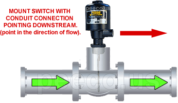
Installation Notes
All minimum actuation points are based on the switch being installed vertically (within 5° of vertical) in a horizontal pipe. Other installations must be called out at time of quotation. Switches will not work properly in turbulent flow — recommend a minimum of 10 pipe diameters of straight run in front of the switch and 5 pipe diameters after. All switches must be adjusted after installation unless a 3rd party calibration has been requested.
Need help selecting the right flow switch for your application?
Submit a Request Form