Flow Switches Made in the U.S.A. · Serving Industry Worldwide


Technical Reference
Electrical Data
Meeting electrical requirements is a matter of correct micro-switch selection. PEECO uses premium, large snap-action switches with precise operating characteristics and enhanced service life.
Standard & Optional
SPDT Micro-Switch Options
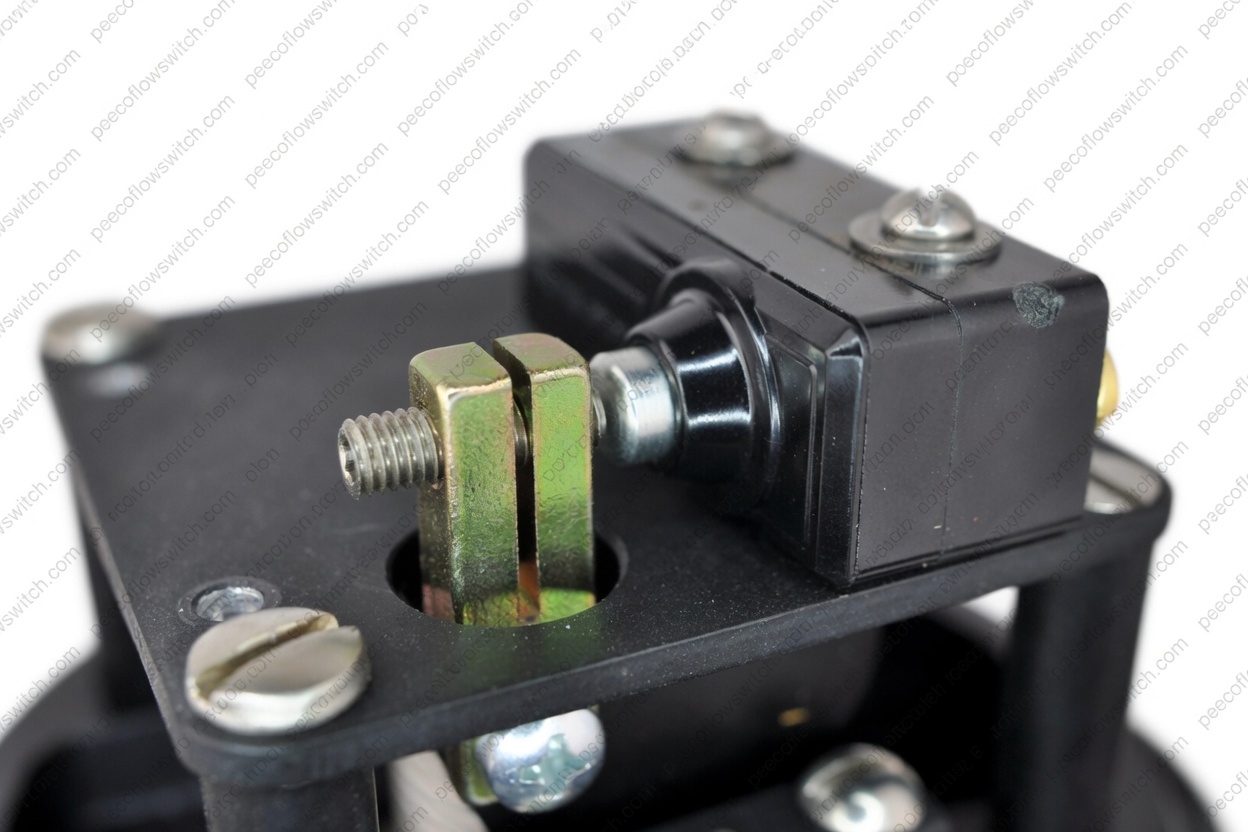
SPDT Micro-Switch
The standard switch supplied with every PEECO flow switch. A large snap-action SPDT micro-switch with precise operating characteristics and long service life. Provides one normally open, one normally closed, and one common terminal.
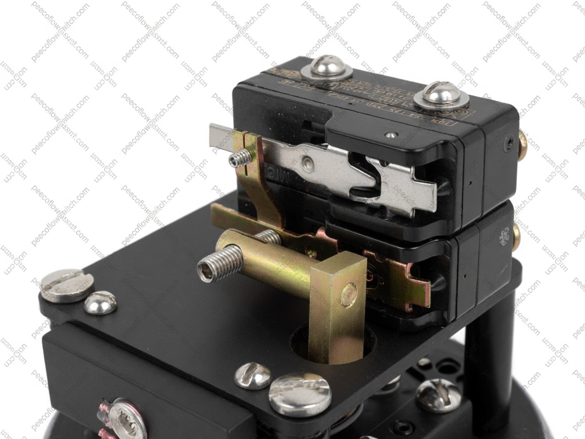
Stacked SPDT Micro-Switches
Two or more SPDT micro-switches stacked on a single actuator for applications requiring multiple independent switching circuits — alarm, shutdown, and control — all triggered at the same flow set point. Available in 2, 3, or 4 switch configurations.

Bi-Directional SPDT
Two SPDT micro-switches configured for bi-directional flow detection. One switch actuates on forward flow, the other on reverse flow — ideal for processes where backflow must be detected and alarmed independently.
Hermetically Sealed Switches
MIL-S-8805 · –67°F to +180°F · Maximum sealing for demanding environments
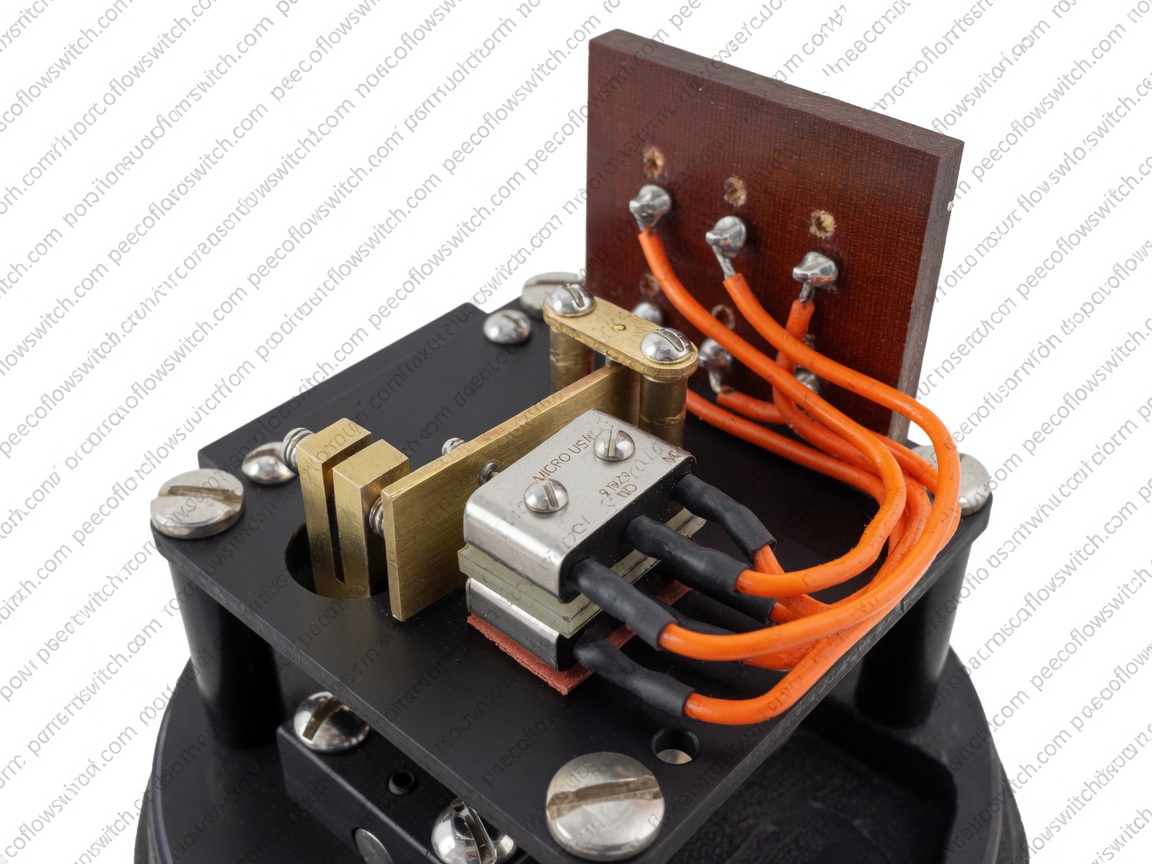
Designed for applications where maximum electrical rating and maximum sealing are essential. Sealed per MIL-S-8805, design symbol 5 (–67° to +180°F or –55° to 82°C). Constructed to military standard specifications. Required in environments where corrosive gases, high humidity, or explosive atmospheres could degrade or ignite an unsealed switch.
Standard SPDT Specifications
Additional Switch Options
- 10A 125 Vdc SPDT (optional)
- 5A 480 Vac 400°F SPDT (optional)
- 15A 600 Vac SPDT (optional)
- 10A 125 Vac DPDT (optional)
- 5A 125 Vac SPDT Hermetically sealed (optional)
- 1A 125 Vac SPDT Hermetically sealed (optional)
International Approvals
ENEC and CE recognized. Over 75 years of engineering excellence. Industry-leading temperature range: up to 204°C [400°F] and as low as –55°C [–67°F].
Configuration
TopWorks Options
Multiple Action
By special use of two or more (up to 6) micro-switches, indicates combinations such as flow/no-flow, two different flow actuation points, or flow/reverse flow.
DPDT Option
Two SPDT micro-switches stacked to provide DPDT function. Available for applications requiring dual-circuit switching.
Air Operated
Where electrical contacts are not permitted or where pneumatic operation is preferred. Supply pressure: 3 to 20 psi or 20 to 125 psi.
Dash-Pot Option
Delays switch action up to 30 seconds to avoid false actuation due to cavitation or turbulent flow conditions.
Hazardous Location & Warning Light Options
For installations in Class I Division 1 hazardous locations, PEECO flow switches are available with explosion-proof housings (E Series and H Series). These models use the same micro-switch options listed above but are housed in UL/CSA-listed explosion-proof enclosures rated for flammable gas and vapor environments.
NEC Compliance: All wiring in hazardous locations must comply with NEC Article 501 for Class I Division 1 installations. Conduit seals are required within 18 inches of the switch enclosure.
Electrician's Reference
Understanding Micro-Switch Terminology
A plain-language guide to the switch types and wiring connections used in PEECO flow switches — for engineers, electricians, and anyone specifying or installing a unit in the field.
SPDT
Single Pole Double Throw
The standard micro-switch supplied with every PEECO flow switch. A single switching element — one pole — that can connect to either of two output circuits depending on whether the paddle is actuated or at rest. Think of it as a single-pole light switch that toggles between two positions: one circuit is energized when flow is present, the other when flow is absent.
DPDT
Double Pole Double Throw
Two independent SPDT switching elements — two poles — operated simultaneously by the same actuator. Each pole has its own set of NO, NC, and Common terminals, giving you two completely isolated switching circuits from a single actuation point. Commonly used when a single flow event must trigger two separate, electrically isolated actions.
Hermetically Sealed
Sealed Internal Contacts
A micro-switch whose internal contact mechanism is completely sealed inside a welded metal enclosure — no air, moisture, or contaminants can reach the contacts. Required in environments where corrosive gases, high humidity, or explosive atmospheres could degrade or ignite an unsealed switch.
NO · NC · Common Connections
Every SPDT micro-switch has three terminals. Understanding how they behave — and how qualified electricians wire them — is essential for correct installation.
Common (C)
The shared terminal — always connected to either NO or NC depending on paddle position. The incoming power supply or signal wire is typically landed here.
How electricians wire it: The line-side conductor (hot wire or control voltage) is connected to Common. This makes Common the reference point from which the switch routes current to either the NO or NC terminal.
Normally Open (NO)
Open (no continuity) when the paddle is at rest — no flow. Closes (completes the circuit) when flow actuates the paddle. Current only flows through this terminal when the switch is tripped.
How electricians wire it: The load — pump motor starter, solenoid valve, PLC input, or alarm relay — is wired to NO when the device should energize on flow. This is the most common wiring configuration for flow-proving applications.
Normally Closed (NC)
Closed (continuous circuit) when the paddle is at rest — no flow. Opens (breaks the circuit) when flow actuates the paddle. Current flows through this terminal at all times except when the switch is tripped.
How electricians wire it: The load is wired to NC when the device should de-energize on flow, or when a loss-of-flow alarm is needed — the circuit stays energized during normal no-flow conditions and opens the moment flow is detected.
Important: All wiring of PEECO flow switches must be performed by a qualified licensed electrician in accordance with the National Electrical Code (NEC), applicable local codes, and the installation instructions supplied with the unit. In hazardous locations, wiring methods must also comply with NEC Article 501 for Class I Division 1 installations.