Flow Switches Made in the U.S.A. · Serving Industry Worldwide


Technical Reference
How to Install a
PEECO Flow Switch
Proper installation is critical to accurate, reliable flow switch performance. Follow these guidelines to ensure correct actuation, long service life, and safe operation.
Standard Mounting Configuration
Vertical mount on horizontal pipe — the default and recommended installation
Note: Switches will not work properly in turbulent flow. Always provide adequate straight pipe run. Other mounting orientations (horizontal, angled) must be specified at time of quotation and may require special configuration.
Installation Steps
Select the Correct Location
Install the flow switch in a straight run of pipe with a minimum of 10 pipe diameters of straight run upstream and 5 pipe diameters downstream. Avoid installing near elbows, valves, reducers, or other flow disturbances that create turbulence.
Verify Mounting Orientation
Standard installation is vertical mounting on a horizontal pipe run (switch body pointing up, paddle hanging down into the flow). Other orientations are available but must be specified at time of order. The switch must be installed within 5° of vertical unless otherwise engineered.
Install the Flow Switch
For threaded (NPT) models: apply thread sealant and hand-tighten, then wrench-tighten to the appropriate torque. For flanged models: align the flange, install gasket, and torque bolts evenly in a cross pattern. For wafer tee models: insert between flanges per the dimensional drawing.
Verify Flow Direction
Confirm that flow direction through the line matches the arrow or label on the switch body. Reverse flow will not actuate the switch correctly. For bi-directional (multiple action) models, flow direction is less critical — consult your order documentation.
Make Electrical Connections
Route conduit to the 1/2″ FNPT conduit connection (3/4″ and metric available). Connect wiring per the terminal diagram on the nameplate. Standard SPDT: N.O. (Normally Open), N.C. (Normally Closed), and Common terminals. Verify voltage and current ratings match your application.
Adjust the Set Point
All PEECO flow switches are fully field-adjustable. With flow established, adjust the set screw to the desired actuation point. The switch should actuate cleanly with less than 10% dead band between make and break. Re-check adjustment after system reaches operating temperature and pressure.
Installation Requirements
Important Warnings
Field Adjustment
All PEECO flow switches must be adjusted after installation unless a third-party calibration has been requested and provided at time of order. The switch is fully field-adjustable across its entire operating range.
Water and nitrogen are used for factory flow testing to establish minimum activation and deactivation points. Field conditions (media, temperature, pressure, specific gravity) will affect the actual actuation point — use the velocity correction factors in the Flow Rate Table when working with fluids other than water.
Set Screw Adjustment
The set screw controls the tension on the return spring, which determines the flow velocity required to actuate the switch. With flow established at the desired trip point:
Spring Selection
PEECO flow switches are supplied with a standard spring matched to the ordered flow range. If the set screw has been adjusted to its full range and the switch still cannot be set to the desired trip point, a different spring rate is required. Springs are available in multiple rates to cover low, standard, and high flow applications.
Changing the Spring
Spring replacement is a straightforward field procedure. De-energize and isolate the switch before opening the cover.
- 1Isolate the line and de-energize the switch. For E and H Series, follow hot-work procedures before removing the cover in a hazardous area.
- 2Remove the cover (slip-off for N Series; unscrew for E and H Series — five threads minimum engagement when reinstalling).
- 3Back the set screw out fully to release spring tension before attempting to remove the spring.
- 4Note the current spring position and orientation before removal.
- 5Remove the existing spring and install the replacement. Confirm the spring seats correctly against the actuator arm and the set screw bearing surface.
- 6Re-install the cover. Re-establish flow and adjust the set screw to the desired trip point.
- 7Verify actuation and reset at operating conditions before returning the switch to service.
Do not modify the spring by cutting, stretching, or bending it. A modified spring will not provide consistent force across its travel range and will cause erratic actuation. Always replace with a factory-supplied spring of the correct rate.
Understanding the PEECO Micro-Switch
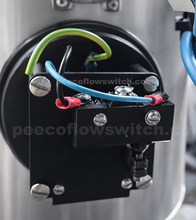
PEECO Flow Switches use a standard 15A SPDT micro-switch to detect paddle movement. Understanding how its contacts operate is essential for correct wiring — the PEECO mechanical design reverses the expected contact states relative to flow.
1. The Three Electrical Terminals
The PEECO standard 15A micro-switch is a Single Pole, Double Throw (SPDT) device with three terminals. The PEECO installation manual identifies these as terminal D (Common), terminal E (Normally Open), and terminal F (Normally Closed).
| Terminal | Name | Function |
|---|---|---|
| COM | Common | Shared terminal that connects to either NO or NC. |
| NO | Normally Open | Connected to COM when the plunger is depressed. |
| NC | Normally Closed | Connected to COM when the plunger is released. |
The NO and NC designations refer to the contacts' positions when the micro-switch plunger is in its normal, unactuated position — not to whether the contacts are open or closed when there is no flow through the pipeline.
2. How a Standard Micro-Switch Operates
Before examining the PEECO assembly, it is helpful to understand the micro-switch independently. The switch itself operates identically whether installed in a PEECO Flow Switch, a pressure switch, a limit switch, or any other mechanical control device.
Plunger Released (Unactuated)
When nothing is depressing the plunger, COM is connected to NC and disconnected from NO. Current can flow between COM and NC.
Plunger Depressed (Actuated)
When the plunger is depressed far enough, the internal snap-action mechanism transfers the connection. COM disconnects from NC and connects to NO.
What makes the PEECO application different is the way its mechanical linkage operates the plunger — described in the next section.
3. How the PEECO Design Operates
An important characteristic of every PEECO Flow Switch is that its micro-switch plunger is depressed in the no-flow position. The paddle, return spring, and adjustable actuating rod are arranged so the plunger is held down when the paddle is at rest.
This means the electrical contact arrangement is opposite what someone might expect when interpreting the NO and NC designations as descriptions of the process conditions.
No Flow — Plunger Depressed
Flow Established — Plunger Released
For a PEECO Flow Switch: the NO contact is CLOSED when there is no flow, and the NC contact is CLOSED when flow has reached the trip point.
4. Electrical Contact Reference Table
| Flow Condition | Plunger | COM–NO | COM–NC |
|---|---|---|---|
| No flow | Depressed | CLOSED | OPEN |
| Increasing flow, below trip point | Depressed | CLOSED | OPEN |
| Flow reaches trip point | Released | OPEN | CLOSED |
| Flow established above trip point | Released | OPEN | CLOSED |
| Flow falls below reset point | Depressed | CLOSED | OPEN |
5. Selecting the Correct Terminals
Signal when flow is established → Use COM and NC
When the pipeline is not flowing, the circuit is open. When flow reaches the setpoint, the plunger releases, closing the circuit between COM and NC. The PLC or control panel receives the signal that flow has been established.
Signal when flow is lost → Use COM and NO
During sufficient flow, the circuit is open. When flow falls below the reset point, the return spring moves the linkage, depressing the plunger. The circuit between COM and NO closes, activating the alarm or interlock.
| Customer Requirement | Terminals | Circuit Closes When |
|---|---|---|
| Flow confirmation | COM + NC | Flow reaches trip point |
| Low-flow / no-flow alarm | COM + NO | Flow falls below reset point |
| Signal for both states | COM + NO + NC | Each circuit responds to its respective contact state |
These examples describe the switch's contact behavior. The complete system's response to a broken wire or loss of control power depends on the wiring and controller design.
6. Does the Micro-Switch Supply Electrical Power?
No. The PEECO standard 15A micro-switch is a mechanical switching device. It does not generate voltage or provide its own electrical power. The three terminals function as externally powered electrical contacts.
For example, if 24 VDC is connected to the COM terminal: during no-flow conditions that voltage is available at NO; when flow reaches the trip point, the connection transfers and the voltage becomes available at NC. The switch simply directs an externally supplied electrical signal between two possible paths.
7. Testing with a Multimeter
Electrical contact operation can be verified using a multimeter in continuity mode. Disconnect electrical power and isolate the switch from the connected control circuit before testing.
Resting / No-Flow Position
| Test | Expected |
|---|---|
| COM → NO | Continuity |
| COM → NC | No continuity |
Flow-Actuated Position
| Test | Expected |
|---|---|
| COM → NO | No continuity |
| COM → NC | Continuity |
When the paddle returns to its resting position, the contacts should return to their original no-flow state. Actual flow setpoint verification should be performed under operating conditions using the appropriate flow measurement.
Troubleshooting
Most field problems trace back to one of six root causes. Expand each symptom below for likely causes and corrective action.
Still having trouble?
Our engineering team provides free technical support for all PEECO installations.
Ready to Order Your Flow Switch?
Every PEECO flow switch is custom-engineered for your application. Submit your process conditions and receive pricing and delivery typically within one business day.
Request Pricing & Delivery